Friday, February 21, 2014

TEK Scope screen is dead

Bad thing just has happened!
I was watching strange signal shape coming out from my just assembled amplifier board when picture on the scope began to jump and scary pops and clicks started to come from my nice scope.
Thunderbolts inside a scope is not a very good sign, right? So another challenge is going to begin.
To be honest I'm not a fan of scope repairing... But high voltage transformer has died tragically.
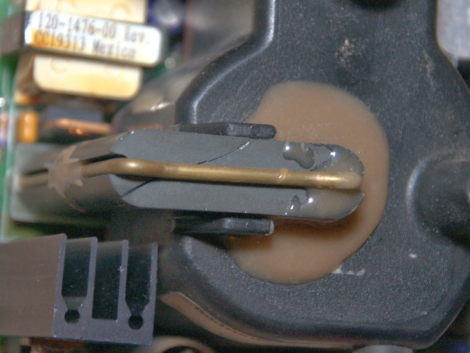
Couldn't find a transformer like that on the Internet, found just a couple of LCD kits for almost thousand bucks. Well, I believe I can do it for less because the scope has a VGA output and it should be possible to connect a regular LCD to it.
I'm afraid a new LCD would not have better picture than CRT had, but I don't have a lot of options.

I know some people who have such color Tektronix TDS scopes have dead CRTs, so maybe I can find such a folk and give my CRT to him...

Sunday, February 16, 2014

Soldered: TAS5631B amp

Here is my first amplifier board completed:

I put SMD inductors vertically while they supposed to lay on the PCB:

I have two good reasons for that - first of, it saves a lot of very limited space and the second - if the warm up it would help them to cool down (questionable, but makes me feel better).

Looks fine. Especially having in mind it is my first SMD project. Let's connect all my stuff together and check if it is able to produce any sound...


Wednesday, February 12, 2014

TAS5548 PWM Modulator board

I started with PWM modulator. What is the reason of soldering the whole amplifier board if PWM doesn't work?
And even more, my setup requires only one PWM modulator board and I have ten available. Plus 5548 has its pins on two sides only which probably can make the soldering a little bit easier.

Well, it was not that scary,
I'm not a soldering guru and I was scared about SMD components, especially chips with 0.5 and 0.6 mm pitch. But it turned out to be not such a big deal. Thanks to Steve from EEVBlog for his video tips on how to solder smd chips.
TAS5548
Not bad for the first try
The only thing I really struggled with is crystal oscillator. It has its pads underneath and I couldn't place it well. But it works and I don't want to re-solder it.

Here is my test setup:
BeagleBone Black + MiniDSP USB Streamer + my PWM modulator:
It is a whole different story how to setup BBB...
Adafruit has python libraries to drive I2C bus so here my first python program ever:
import Adafruit_BBIO.GPIO as GPIO
import Adafruit_BBIO.PWM as PWM
from Adafruit_I2C import Adafruit_I2C
 
def i2cPrint32(x): 
 bytes = i2c.readList(x, 4)
 print "%X %X %X %X" % (bytes[0],bytes[1],bytes[2],bytes[3])

i2c = Adafruit_I2C(0x1A) # see notes about I2C address below

print "5548: 0x%x = %X" % (0x01, i2c.readU8(0x01))

### UnMute
print "============="
print "CTRL:"
ctrl = i2c.readU8(0x03)
ctrl = ctrl & ~0x10
print hex(ctrl)
i2c.write8(0x03, ctrl)


### VOLUME ###
print "Master Volume:"
volume = [0,0,0,0xAF]
x = 0xD9
i2c.writeList(x, volume)
bytes = i2c.readList(x, 4)
print "%X %X" % (bytes[2], bytes[3])
it umutes the modulator and sets some non-zero volume.
And here is the output:
5548: 0x1 = 4
=============
CTRL:
0xa0
Master Volume:
0 AF

After unmute I can see 50/50 PWM duty cycle:
And when input signal is applied:
So looks like it works. On first try!

But there was a caveat with 5548 I2C addresses. My BeagleBone didn't want to work with 5548 chip at the address from its datasheet - 0x34/0x36 (depending on jumper). Luckily Linux has a command to scan I2C buses so my device was found in a couple of minutes (googling):
root@arm:~/py# i2cdetect -r 1
WARNING! This program can confuse your I2C bus, cause data loss and worse!
I will probe file /dev/i2c-1 using read byte commands.
I will probe address range 0x03-0x77.
Continue? [Y/n] y
     0  1  2  3  4  5  6  7  8  9  a  b  c  d  e  f
00:          -- -- -- -- -- -- -- -- -- -- -- -- -- 
10: -- -- -- -- -- -- -- -- -- -- 1a -- -- -- -- -- 
20: -- -- -- -- -- -- -- -- -- -- -- -- -- -- -- -- 
30: -- -- -- -- -- -- -- -- -- -- -- -- -- -- -- -- 
40: -- -- -- -- -- -- -- -- -- -- -- -- -- -- -- -- 
50: -- -- -- -- UU UU UU UU -- -- -- -- -- -- -- -- 
60: -- -- -- -- -- -- -- -- -- -- -- -- -- -- -- -- 
70: -- -- -- -- -- -- -- -- 
I put this address 0x1A into my python script and voila!

So it's time to build an amplifier board.

Sunday, February 2, 2014

PCBs arrived

Oh my! They are gorgeous!
I must think this way because they are my first SMD-PCB-babies. And I have ten of them, so I have enough spare ones if I mess one up.


Right away I found a wrong label: "5431 Amp v.1.0". OK, let's put it this way - "it was made intentionally to confuse enemies".

Wednesday, November 20, 2013

Scope Cleaning

All capacitors were removed with "twisting" method. I don't have hot tweezers to desolder large SMD capacitors and I'm afraid I would damage more pads if I used a single soldering iron. Almost all the traces left in place, I lifted just two pads which is not bad having almost hundred caps and all these leakages which could damage everything around.

After all capacitors were removed I had to clean all the acid residue. I found a lot of PCB cleaning stories. Seems that most popular way is to use Simple Green general purpose cleaner.
Simple Green + toothbrush + baking oven at about 150F made it virgin clean.

All capacitors are replaced with new low ESR leaded ones.
Before caps replacement

After all the caps are replaced. Still have Acquisition board fail...

Error log shows a mysterious error
I still have failed acquisition test, but scope seems to be working. 

Unfortunately I couldn't find where the problem can be. The only suspicious area is around U1602, where were a lot of corrosion. I replaced this opamp with a new one but could not find where one of the legs connected. Seems to be a broken trace. I would be happy to fix it but could not find where to connect it. Need to try to find out...
It  looked not very nice...

But I think I can live with non-calibrated scope.

Friday, October 25, 2013

Oscilloscope

Having a multimeter is not enough to build an amplifier. I need an oscilloscope.
Thanks to craigslist, I found a new challenge.
Tektronix-TDS544A. Cool 500MHz digital scope with 4 inputs. But there are some caveats...
Before buying I tried to google it and found that all these scopes have leaking SMD capacitors. Leakage leads to a number of different anomalies.
Seller of mine scope told me the scope powers up but he can't see a thing. Since it is all crap shooting I gave it a try.
As expected, a lot of capacitors have leaks.
The plan is:
1. remove them all
2. clean all the PCBs
3. clean again
4. clean one more time
5. solder new capacitors

Some leaks look very suspicious
The worst leak


let's clean it up

Tuesday, October 8, 2013

Class D?

Among all the passionate discussions taking place on audiophile sites I found that I need to find a sweet point between the money, effort I put in my project, the fun I can get working on it and result (in terms of sound quality) I can get at the end.
Since I'm just an ignorant hobbyist I don't see a point to invest too much in my first project. I want it to be both fun and challenging.

So my amp is going to be fully digital class D amp. No analog circuits at all.

The roadmap is:
1. Play music on a device which has a USB
2. Convert USB to I2S
3. Pass I2S to PWM modulator
4. Feed power stage with PWM from the modulator.
Seems not to be super extremely complex.

I found these nice chips from Texas Instruments:
-  PWM modulator TAS5548
- 300W/channel power stageTAS5631B
last one promises pretty good THD up to 100W, but I don't think I ever need that power, especially having active amplification.
TAS5548 can processes 8 separate channels (4 I2S stereo channels) at 96kHz, has two ASRCs onboard and 7 biquads per channel. So it is able to handle all active crossover filters! I like the idea.

So next step is to design a PCB.